ABC-1451
ABC-1451
Couldn't load pickup availability
- 2 Pcs / 1 Set, Vacuum Bag
- In a specified size range for the cables, it will allow cables to maintain a regular percentage of the section conductor and insulation diameter ratio after complete assembly and also achieve the best transmission effect.
- It’s allow to connect conductor by solder or crimp
- The conduct material is made by high pure copper (beryllium copper) and plated without nickel base.
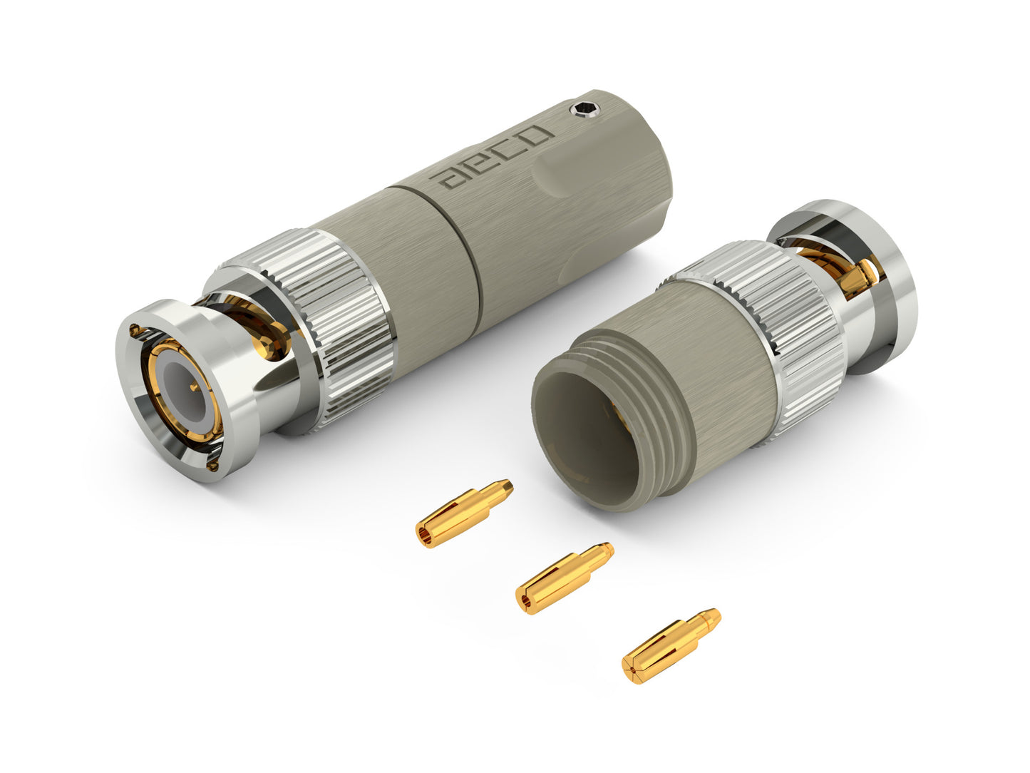
※ The product image is for reference only; the actual shipped product shall prevail. ※
Note
Note
⚠ This product features nickel-free (non-magnetic) plating. Surface wear from regular use is a natural occurrence.
The second contact pin (ID 1.3/0.9/0.5 MM 2 pcs each)
and screw (3MM 2 pcs) which is for locking cable
all including in the pack.
Concept
Concept
Provide much selection of the cable type.
In order to achieve the best transmission effect (VSWR approaches 1) in RF fields, we will concentrate the specifications for the correspondence between connectors and cables.
For example, the Japan specification (4C, 5C) or US specification (RG-59, RG-6U) and other specification and impedance, You must choose the same specification and impedance for the connectors and cables.
The definition of the specifications is to maintain a regular percentage of the section conductor and insulation diameter ratio connection after assembly.
In case of the unclear specification of the cable, it will cause there no corresponding connector.
Under these circumstances, ABC-14 will be proposed a solution on it.
In a specified size range for the cables, it will allow cables to maintain a regular percentage of the section conductor and insulation diameter ratio after complete assembly and also achieve the best transmission effect.
It’s allow to connect conductor by solder or crimp.
The method of main contact pin to suit several secondary contact pin;
Not only to extend the compatibility, also increase the suitable ability of cable and connectors.
Secondary contact pin’s cross cutting and shrink design.Which is able to choose the solder or crimp method to connect the contact cable conductor with contact pin of the connector.
The conduct material is made by high pure copper (beryllium copper) and plated without nickel base.
Focus provide the client who has requirement of Hi-End by highest quality design and material.
Mechanical structure
Mechanical structure
Main contact pin uses the barb hook into the insulation while assemble.
Secondary contact pin fixed with main contact pin while assemble cables by crimp method.
The body and the insulation will used the barb hook to assemble tighten, and fix middle piece shell with punch riveting.
The front shell rivet on the body by spring and washer and it can spin independently.
The end part and middle part of the shell locked by screwing,
and fix with the cable and the sleeve stable by a screw.
Assembly
Assembly
1. Peel cable
1.1 The cable OD < 7.5mm:
Step01
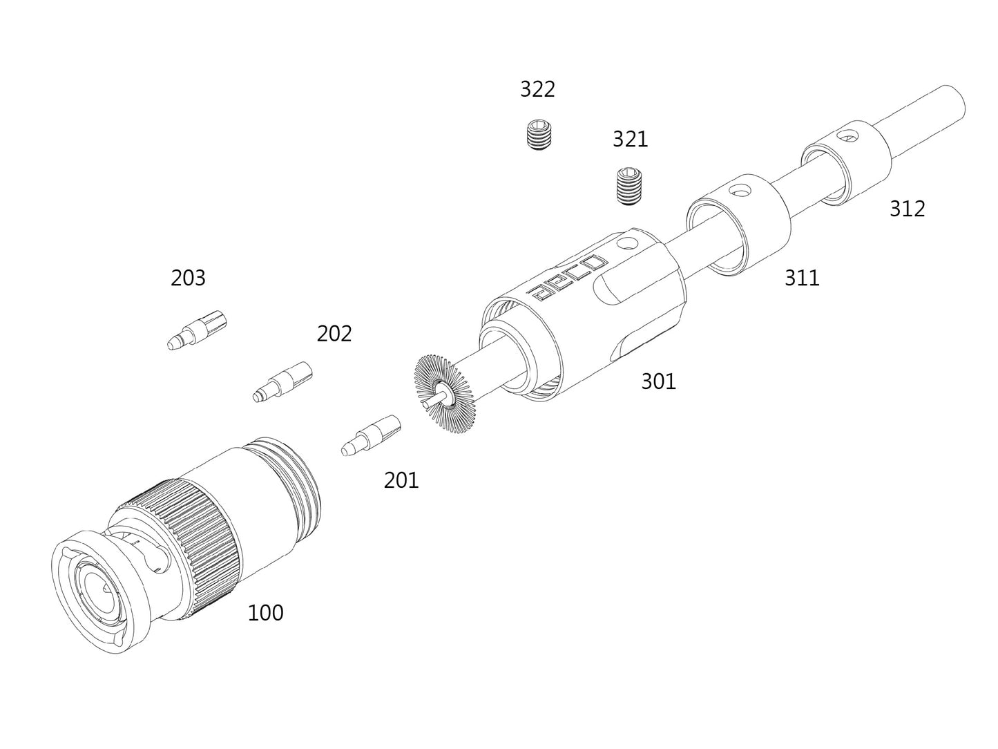
Place shell’s back part<301> in the cable, and removed the sleeve<311/312> depends on the actual cable OD size.
Step02
Peel the shields about 6.0 mm.
Step03
Move out the cable braid and dielectric(X-2)mm, X is the cable OD which include the braids.
Step04
To comb the braids by radial direction, and spread it out with core in vertical direction. And the spread out Round diameter is about 12.0mm. Move out the aluminum foil anddielectric along the braids spread area.
Step05
Make sure the cable core is exposed 3.0mm than braids spread area.
1.2 The cable OD >7.5mm but <10.5mm:
Step01
Peel the shields about 20.0 mm
Step02
Move out the cable braid anddielectric(X-2)mm, X is the cable OD which include the braids.
Step03
Place shell’s back part<301> in the cable, and removed the sleeve<311/312> depends on the actual cable OD size.
Step04
To comb the braids by radial direction, and spread it out with core in vertical direction. And the spread out Round diameter is about 12.0mm. Move out the aluminum foil anddielectric along the braids spread area
Step05
Make sure the cable core is exposed 3.0mm than braids spread area.
2. Contact pin
2.1 To choose suitable ID size based on the second contact pin <201/202/203> of the pack included.
Second contact pin<201> ID will be 1.3mm after shrink.
Second contact pin<202> ID will be 0.9mm after shrink.
Second contact pin<203> ID will be 0.5mm after shrink.
2.2 To polish the chamfer of the cable core surface by chipping or milling
2.2.1 Crimp(no solder): Clamp the second contact pin by tools, and push the second contact pin shrink gap into the cable central conductor.
2.2.2 Solder: Clamp the second contact pin by tools, and solder the second contact pin with the cable core.
3. Place the second contact pin and cable sets in the main contact pin shrink of the shells middle part.<100>
4. Make sure the braids is completely spread out and be radial, to lock the back part of shell <301> into the middle part of the shell.
5. To fixed the cable from shell’s back part with screw<321/322>
Specification
Specification
Material:
Contact Pin: beryllium Copper (C17300 / copper contain 97% at least)
Body: Brass Zinc alloy (C3604)
Spring: Steel
Washer: Steel
Shell: Brass Zinc alloy(C3604)
Screw: Stainless Steel(SUS304)
Finish:
Contact Pin: 10u" gold plating (no nickel base)
Body: 10u" gold plating (no nickel base)
Spring: Nickel plating
Washer: Nickel plating
Shell: Satin nickel plating + topcoat
Screw: Nature
Electrical Characteristics:
Impedance: 50 ohms
Frequency Range: 1GHz
VSWR: up to 1.2
Contact resistance < 0.1 mOhm
Dimension:
Cable hole without sleeve: 10.5mm
Cable hole with sleeve: 6.5/8.5mm
Biggest OD: 14.5mm
Total Length: 42.0mm
The corresponding of the cable size:
Center conductor < 1.5mm
Insulation OD > 3.0mm
Woven shield OD > 7.5mm
Outer plastic sheath OD < 10.5mm
Recommend soldering temperature
Recommend soldering temperature
Temperature Soldering Iron, please keep 350 °C within 20 second.
Temperature Soldering Iron, please keep 400°C within 15 second.
Temperature Soldering Iron, please keep 450°C within 10 second.
Product production process comply with RoHS.
1 Year Warranty Included
Share